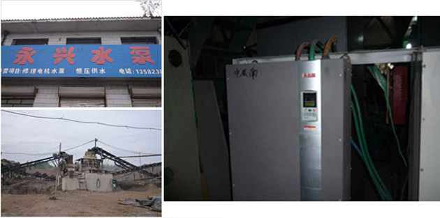
Constant pressure for water pump belongs to the constant pressure water supply equipment, has a subsidiary in internal small pump function, no more than a small pump in water water yield have attached small pump water supply pressure, when the water more than small pump water yield, through the pressure sensors' inner fluid pressure drop, after analysis of the microcomputer controller output signal to frequency converter according to the results of the computation again, frequency is controlled by inverter main pump running and according to the water pump sets, thus greatly saving energy and water saving.

System composition
The early constant pressure water supply system is generally based on PLC or single chip microcomputer, with complex control equipment to achieve. With the continuous development of inverter technology and continuous improvement of functions, simple constant pressure water supply system is no longer dependent on PLC or single-chip microcomputer control system. This control task can be realized only by the built-in function of frequency converter. The speed control of the motor can be realized by using the PID closed-loop control function of the inverter and the pressure sensor as the feedback device. Thus, the water supply pressure is constant.
System function
In the past constant pressure water supply equipment, often used with the mode in/out programmable controller or PID regulator, PID algorithm programming difficulty, equipment cost is high, difficult to debug. The inverter with built-in PID control function is used as the main control equipment of constant pressure water supply equipment, which reduces the equipment cost, improves the production efficiency and saves the installation and debugging time. At the same time, in order to ensure the accuracy and loss of water pressure feedback signal value, the signal can also be set filter time constant, the feedback signal conversion, so that the system is very simple and convenient for debugging.
After analysis, we choose AMB-100 series inverter.
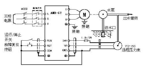
Through the analysis of the whole system, we choose the amb-100 series inverter produced by ambition company, which is a high quality, low noise, multi-functional universal frequency converter for various working conditions. Built - in PID regulator, closed - loop control system structure is simple. We choose ytz-150 potentiometer type remote pressure gauge, installed in the water pump outlet pipe, the pressure gauge is suitable for the general pressure gauge applicable to the working environment, not only can directly measure the pressure value, but also can output the corresponding electrical signal, the output electrical signal to the far inverter. The pressure gauge has red, yellow and blue leads.
Simple wiring diagram of constant pressure water supply system

Because the drainage pressure of the pump is proportional to the second revolution, the pump speed control to maintain pressure, to achieve the water supply effect. At present, it is the most ideal and economical method to adopt frequency converter to control the speed of pump motor. The application of inverter to the constant pressure water supply system not only reduces the installation labor intensity of engineers, but also shortens the debugging time, facilitates the use of users, reduces the investment, saves the electric energy, shortens the equipment maintenance time and improves the economic benefit. At the same time, the various protection functions of frequency converter can protect the motor well.
1. It is not necessary to install ac contactor between the output terminal U, V and W of the inverter and the motor, otherwise, during the operation of the inverter, if the contactor is ON and OFF, large current and overvoltage will be generated. Easy to damage the inverter bridge power module in the inverter. In addition, it is generally unnecessary to install thermal relay for overload protection (except when one inverter drives multiple motors).
2. The ratio between the rated capacity of the converter and the rated power of the motor should be 3:2. The output which affects the effective torque is reduced, and the content of higher harmonics is increased.
3. The control cabinet of frequency converter shall be installed in a dry and well-ventilated place and shall avoid direct sunlight.
4. When the temperature reaches above 40 C, the ventilator shall be installed correctly in the inverter control cabinet. The exhaust fan shall be installed in a downward and upward manner to ensure positive pressure ventilation in the variable frequency control cabinet.
5. When the motor is running at low speed, ventilation and cooling measures shall be taken when necessary for heat dissipation.
6. When measuring the insulation resistance of the motor with the insulation resistance meter (megohm meter), disconnect the inverter terminals U, V and W from the motor connection. Do not apply the test voltage to the inverter, because the voltage is too high, it is easy to cause the inverter damage.
7. When the output frequency of the inverter is low, the output voltage is low and the voltage drop ratio is large. Therefore, the cross-sectional area of the cable is one step larger than that of the cable with no frequency converter as the driving motor. The cable length should be as short as possible. It is not allowed to be laid together with the control line (except the shielded line).
8. In order to prevent electric shock and effectively suppress rf interference, the inverter housing shall be well grounded.
|
|

|
| The public, | Mobile station |
 0755-81719517
|
|
 0755-81719530 0755-81719530 |
 [email protected] [email protected] |
 Floor 1, 5 and 6, building 7, lijincheng science and technology industrial park, gongye dong road, longhua new district, shenzhen Floor 1, 5 and 6, building 7, lijincheng science and technology industrial park, gongye dong road, longhua new district, shenzhen |
|